April 25, 2013
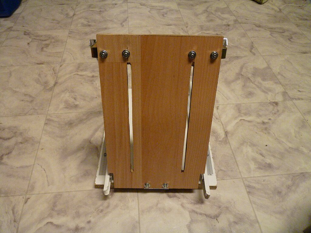
Built monitor supports for my MIP.


Bottom part - piece of standard particle board shelf. 300 x 260 mm

Top part - leftovers from laminate floor board 8 mm thickness, 185 x 260 mm.

Pair of standard 2.5" angle brackets from hardware store. One standard hinge.

Moving parts: standard 300 mm drawer sliders $3.79 for pair (4 parts).

There is a 8#x32 machine screw installed on the angle support side for fixing the position.
Slots (100 mm between) were cut with miter saw.
Connecting piece - aluminum U-channel profile 26 cm length.
With the above dimensions the assembled support already provides ~72 degree angle, which matches my MIP angle. The actual required slide travel range is small - just for some adjustments.
This design should fit any 737 MIP monitor installation. My monitors are two 18.5" Acer and 15" Dell. You might need to check where power and VGA connections are on your monitor to make sure the support does not obstruct them.


August 22, 2013
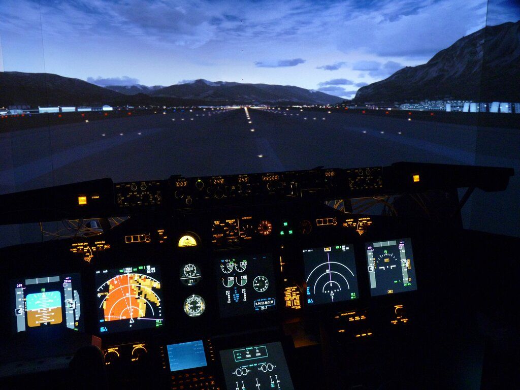
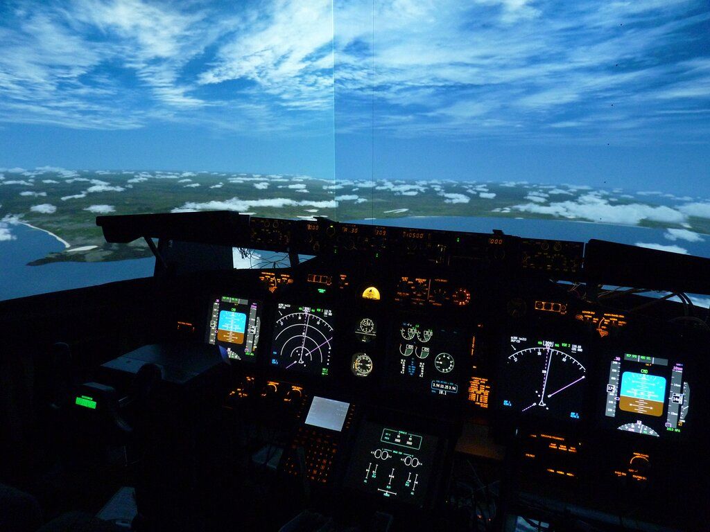
MIP is functional!
Finally, (7 month later than scheduled ) I have functional MIP.
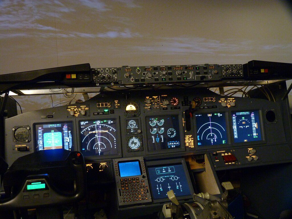
FDS Signature panels, homemade dimmable backlighting.
MIP is controlled by two Pokeys55 cards, Prosim 737, Jetstream flight model.
Here are the pictures:
Lights test:

Ready to roll:

In flight:


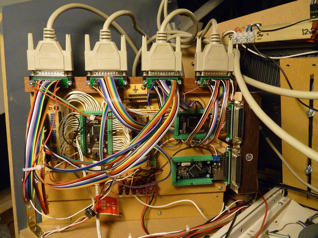
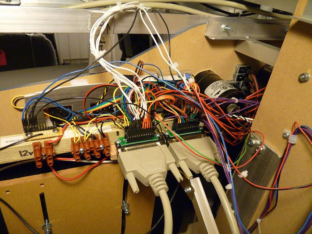
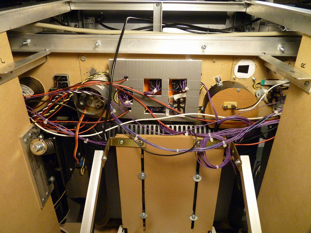
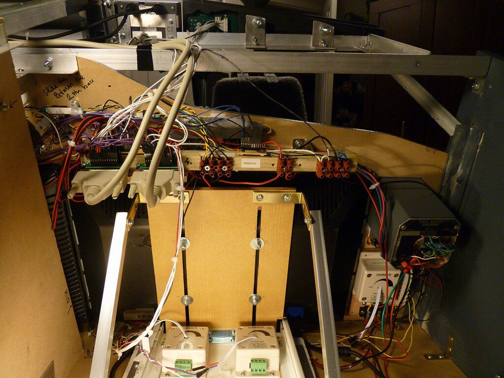
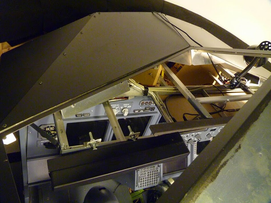
The inside:
I never liked and idea of directly soldering huge tails of wires running between MIP elements and control card. My thanks to Axel (N737AG), who pointed me to the right direction!
So here is my fully modular design Any MIP subpanel can be easily disconnected and removed in minutes for maintenance or repairs.
The control module with Pokeys 55 cards and LED extension boards (homemade) is connected to actual MIP controls by 4 standard DB-25 cables.

One Pokeys55 operates all annunciators (and two F/O DU brightness inputs) and another one operates all switches (and 4 CPT side DU brightness inputs).
Main computer in addition to visuals runs Prosim 737 System module and Prosim MCP.
Two notebooks are located in MIP and currently run:
First one runs Prosim Display for Captain side and Upper EICAS.
Second one runs Prosim Display for F/O side, lower EICAS and Prosim CDU.
Notebooks are located in the Captain side of MIP above pedals area on the pull-out shelves.


I have third notebook there which is not used yet.
Three sections of MIP compartment accessible from behind:


More details later.
December 24, 2013
What MIP and Christmas have in common?
Yes, MIP may look like lit up Christmas tree:

Yet there is another more direct connection.
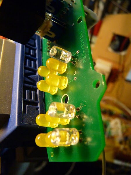
My MIP that I bought had annunciator boxes but no LED lights/panels. So I needed some DIY solution. And I bought nice panels from Opencockpits. Then, for the actual LEDs I turned my eyes to cheap and inexhaustible source - Christmas lights.


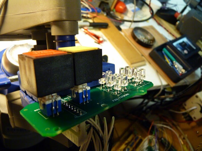
The LEDs from Christmas lights are typically for 3.1-3.6 v, so they will not work well with FDS cards - they will be too dim. But they are perfect solution for those who use Pokeys cards. However, Pokeys itself can guarantee only 4 ma current per output, so LED lights need LED extension board that can be build yourself, like I did:


or such board can be bought from www.flightsimparts.eu
Note also, that Pokeys card outputs need a common plus, not ground. In case of using LED extension boards the outputs go through ULN2803A chip then limiting resistor (560 Ohm in my case for +12v) then through DB-25 cable to MIP that has common +12v connector for LEDs.
Another detail is that Opencockpits annunciator LED panels have pair LED connection in series, not in parallel like FDS cards do.
I actually had to rework my FDS 6-packs when I decided to replace LEDs in them to the ones from Christmas lights. I had to reverse the LEDs so they could have common + instead of common ground. Those 6-pack LEDs are powered from dedicated 5-volts LED Extension board (with 120 Ohm resistors), as well as AFDS single LED lights.
So, this is how Christmas lights are connected to MIP. Now would be a good time to get them on sale.
**************
Some other small additions to that version of FDS MIP panels. I installed additional annunciators for "Takeoff Config and "Cabin Altitude" both on Captain and F/O sides. And "Autoland" annunciator on Captain side.
****************************************************************************************************
January 14, 2015
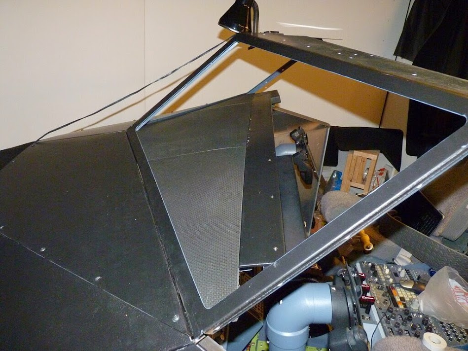
Glareshield trim made easy.
Finally I completed (more or less) my glareshield trim.
I have custom made glareshield structure that made from standard aluminum angle profiles - that's what I obtained with the MDF MIP structure.

There are no special casings for MCP and EFIS - they are just attached on aluminum holders. Glare wings with six-packs are from FDS. I reinforced the glareshield structure even more, so one can probably hang on it. :)
But there were no top shield trim and underwings.
I was recommended to use the Coroplast lightweight sheets that come in different colors and even bought a black one. But after more consideration I decided to look for something else. The contenders were the rubber foam floor cover (that I am going to use for cockpit floor cover anyway) and similar (but thicker) grey rubber foam floor mats (set of 4) that can be bought almost anywhere for about $12. After several tries floor mats won.

I also needed the panel piece that goes over MCP and has the AFDS lighting attached. Its thickness should be something like ~ 5 mm. In some real cockpit photos I've seen that it may be a separate piece rather than the part of the whole glareshield panel.
So I found a plane standard plastic baseboard in Home Depot and made the plank from it.


It's now attached to the glarewings in front and to the aluminum angle support on the back.


I primed and painted it black.
Next, I carefully cut the three pieces from mats and just connected then with sticky tape on the back.

The size was chosen so they are slightly squeezed in between the window frame and the MIP plank.
The pieces of same baseboard were used as supports. The support pieces just fit in
between window frame ends and attached by doublesided tape to glarewing structure.


So, when necessary, the whole glareshield rubber panel can be removed just by pulling it out. The rubber texture does not have any reflections back to screen.
Next, the underwing tim. This is typically the complex-shaped plastic piece that is difficult to make and fit (or get the original one). I figured that very close in appearance thing can be easily made from same rubber mat.


The piece is not even attached in any way (i.e glue, screws, etc.) It just fits in between FDS glarewing, aluminum MIP glareshield structure and top of Captain and F/O MIP panels. This makes easy access to MCP/EFIS cables and connectors - you just need to pull the trim out and later reinstall it back in seconds.


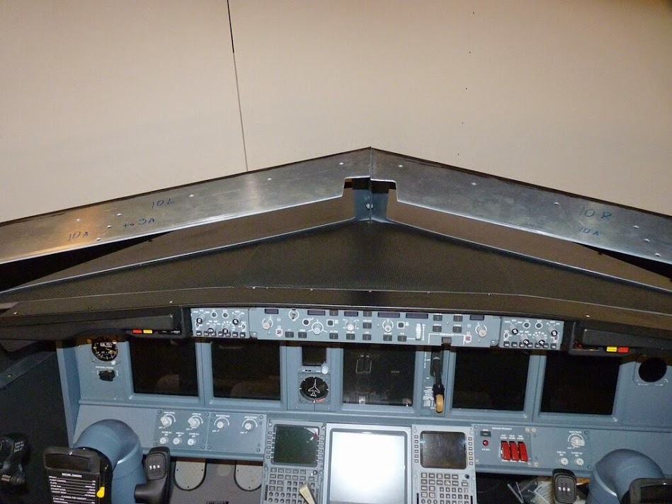
Here is the photo I made for comparison of real MIP and mine look, taken from similar angle and distance. (Left picture is taken from jetphotos.com)

The finishing touch is the glareshield map pocket. So far I just cut it from kitchen cookie pan thingie bought in dollar store.

It's already grey, so not even painting required. Good enough until I find anything better.
And now a few pictures with installed AFDS and MIP lighting.


No comments:
Post a Comment