Motorized Throttle Quadrant.
I received my 737 motorized TQ that Rob (aka 727737Nut) worked on for a while.
Here are pictures made by Rob during conversion:


TQ in my workshop:

I had to rework the base to accommodate the TQ "tail" under the base floor:


and reinforce the "tail" since what's left from its aluminum frame flexed a lot.

Now TQ already can be installed in the base. It can slide in the fittings back and forts as necessary, since the position of MIP/TQ/pedestal will change when the FDS shell is installed. I do not have the shell yet.
TQ motorization.
The hardware part of my 737-300 throttle motorization was done by Rob Archer, aka 727737Nut.
Rob also suggested me to use Opencockpits cards, since he worked with them himself.
However, when I looked at SIOC script language closely I felt, well, SI...CK :) . As a professional programmer I just wanted something more versatile, where I have more control on things, and decided to go with .Net (C#).
So, my electronic blocks of choice changed to:
Pokeys 56 (USB).
Phidgets 1064 2-motors card for throttle levers (DC motors)
Phidgets 1065 1-motors card for trim wheel (DC motor)
Phidgets 1061 8-servo card for speedbrake, trim indicator and flaps indicator.
Electronic relays for servos to disconnect servo power when servo is in idle mode.
All these cards have DLL libraries for .Net and sample .Net projects are availabe.
I placed Phidgets motors cards on a small panel that easily swings out from inside the TQ.


Phidgets Servo card is located inside the speedbrake servo housing in front of TQ.

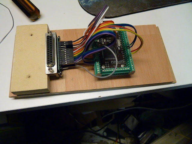
Pokeys card is on the MIP control block, connected to TQ by DB25 cable. I worked on TQ in my workshop, not in the sim itself, so I just connected it to another Pokeys 55 card for tests.

Throttle levers are run by DC motors (I use 12v for them.). Trim wheel motor runs from 25v. Phidgets Servo card needs anything in 6-15 v range, so I also feed 12v to it.
All analog and digital inputs from TQ go to Pokeys card.
The reading cycle for Pokeys and FSUIPC values is set to 100 milliseconds in my software controller which seems to be optimal. (it's a configurable parameter in app.config).
Reverse mode is working now, and I also enabled and tested my trim wheels.
Had a little problem - it turned out that you cannot have Trim Up/Down gates values in Prosim 737 if ProSim MCP is not running.
I redirected Trim Up/Down gates to two Pokeys outputs and read their state in my program, then run the trim motor in corresponding direction (or stop) through Phidgets card basically with one line of code.
My TQ software controller is a visual .Net application that I wrote myself. It allows monitoring all neccessary readings from Pokeys and FSUIPC (besides direct TQ control functions). It is also used as TQ test application, allowing refining all the parameters and logic very easy.
Same application is also used for potentiometers calibration. Overall, all TQ functionality is a combination of my custom .Net application that uses Pokeys, Phidgets and FSUIPC DLL libraries ProSim737 communicates with controller through Pokeys card.
More on TQ software controller is here.
TQ Power consumption
My whole TQ eats no more than 25 watts at peak when trim and levers are moving. Backlighting included. I have standard 200 watt computer PSU for it, feeding 12v and 5v, which by itself eats ~6 watt in idle mode. So any computer PSU will do - and there will be plenty of power left for other needs.
For Trim motor I just use the 25v power brick from the old electric drill. It's 1 Amp only. but that's more than enough. When trim motor works - it eats only 6 watts.
January 25, 2014
Just finished interfacing the trim wheel and trim indicator. Trim wheels are two-speed now, I will think about the logic I need for 4 speeds.
Trim indicator works through the Phidgets 1061 8-servo card. Currently I have only 3 servo for it - trim indicator, speedbrake and flaps indicator.
Configuring servo for trim indicator was very easy. I used Advanced Servo-Full test project supplied by Phidgets.

All I needed was to run it, select the proper servo from the list, click on Engage checkbox and move the Set Target Position slider to find out the proper needle movement range. In my case full needle range from Nose Down to Nose Up is 0 to 16 which corresponds the servo position range 128 to 0).
Then I just wrote the code that recalculates the trim position into servo position.
I read trim indicator position from ProSim through custom FSUIPC offset.
Initially I had relays that turned servo power on/off. However, they were removed since Phidgets servo object had .Engage property for the same thing done programmatically.
Funny observation.
Speaking of trim wheels an indicators - every source mentions horizontal stabilizer and trim indicator going up/down and trim wheels rotation in different directions.
So far I did not find a single manual that makes a connection between the two for a simple question:
When trim indicator moves in "Nose Down" direction - which direction the trim wheels rotate? Clockwise? Counterclockwise?
My take would be that, naturally, I would expect to turn wheels clockwise in order to see the trim indicator needle going to the same direction (nose up).
But I was not able to find any confirmation to that. Even in youtube videos they show just brief rotation of trim wheels back and forth, and it's typically not possible to notice where the actual trim indicator goes.
That's what typically happens when the manuals are written by experts - simple things are so obvious to them, that they forget to mention what you really need to know.
Input from Garys on Cockpitbuilders.com:
During lubrication of the jackscrew we have to move the wheels by hand. I can tell you going from full nose up to full nose down is a workout. The trim wheels follow the needle. In other words if you want to go full nose down they will rotate towards the main instrument panel.
I received my 737 motorized TQ that Rob (aka 727737Nut) worked on for a while.


TQ in my workshop:

I had to rework the base to accommodate the TQ "tail" under the base floor:


and reinforce the "tail" since what's left from its aluminum frame flexed a lot.

Now TQ already can be installed in the base. It can slide in the fittings back and forts as necessary, since the position of MIP/TQ/pedestal will change when the FDS shell is installed. I do not have the shell yet.
TQ motorization.
The hardware part of my 737-300 throttle motorization was done by Rob Archer, aka 727737Nut.
Rob also suggested me to use Opencockpits cards, since he worked with them himself.
However, when I looked at SIOC script language closely I felt, well, SI...CK :) . As a professional programmer I just wanted something more versatile, where I have more control on things, and decided to go with .Net (C#).
So, my electronic blocks of choice changed to:
Pokeys 56 (USB).
Phidgets 1064 2-motors card for throttle levers (DC motors)
Phidgets 1065 1-motors card for trim wheel (DC motor)
Phidgets 1061 8-servo card for speedbrake, trim indicator and flaps indicator.
Electronic relays for servos to disconnect servo power when servo is in idle mode.
All these cards have DLL libraries for .Net and sample .Net projects are availabe.
I placed Phidgets motors cards on a small panel that easily swings out from inside the TQ.


Phidgets Servo card is located inside the speedbrake servo housing in front of TQ.
Pokeys card is on the MIP control block, connected to TQ by DB25 cable. I worked on TQ in my workshop, not in the sim itself, so I just connected it to another Pokeys 55 card for tests.

Throttle levers are run by DC motors (I use 12v for them.). Trim wheel motor runs from 25v. Phidgets Servo card needs anything in 6-15 v range, so I also feed 12v to it.
All analog and digital inputs from TQ go to Pokeys card.

The reading cycle for Pokeys and FSUIPC values is set to 100 milliseconds in my software controller which seems to be optimal. (it's a configurable parameter in app.config).
Reverse mode is working now, and I also enabled and tested my trim wheels.
Had a little problem - it turned out that you cannot have Trim Up/Down gates values in Prosim 737 if ProSim MCP is not running.
I redirected Trim Up/Down gates to two Pokeys outputs and read their state in my program, then run the trim motor in corresponding direction (or stop) through Phidgets card basically with one line of code.
My TQ software controller is a visual .Net application that I wrote myself. It allows monitoring all neccessary readings from Pokeys and FSUIPC (besides direct TQ control functions). It is also used as TQ test application, allowing refining all the parameters and logic very easy.
Same application is also used for potentiometers calibration. Overall, all TQ functionality is a combination of my custom .Net application that uses Pokeys, Phidgets and FSUIPC DLL libraries ProSim737 communicates with controller through Pokeys card.
More on TQ software controller is here.
TQ Power consumption
My whole TQ eats no more than 25 watts at peak when trim and levers are moving. Backlighting included. I have standard 200 watt computer PSU for it, feeding 12v and 5v, which by itself eats ~6 watt in idle mode. So any computer PSU will do - and there will be plenty of power left for other needs.
For Trim motor I just use the 25v power brick from the old electric drill. It's 1 Amp only. but that's more than enough. When trim motor works - it eats only 6 watts.
January 25, 2014
Just finished interfacing the trim wheel and trim indicator. Trim wheels are two-speed now, I will think about the logic I need for 4 speeds.
Trim indicator works through the Phidgets 1061 8-servo card. Currently I have only 3 servo for it - trim indicator, speedbrake and flaps indicator.
Configuring servo for trim indicator was very easy. I used Advanced Servo-Full test project supplied by Phidgets.

All I needed was to run it, select the proper servo from the list, click on Engage checkbox and move the Set Target Position slider to find out the proper needle movement range. In my case full needle range from Nose Down to Nose Up is 0 to 16 which corresponds the servo position range 128 to 0).
Then I just wrote the code that recalculates the trim position into servo position.
I read trim indicator position from ProSim through custom FSUIPC offset.
Initially I had relays that turned servo power on/off. However, they were removed since Phidgets servo object had .Engage property for the same thing done programmatically.
Funny observation.
Speaking of trim wheels an indicators - every source mentions horizontal stabilizer and trim indicator going up/down and trim wheels rotation in different directions.
So far I did not find a single manual that makes a connection between the two for a simple question:
When trim indicator moves in "Nose Down" direction - which direction the trim wheels rotate? Clockwise? Counterclockwise?
My take would be that, naturally, I would expect to turn wheels clockwise in order to see the trim indicator needle going to the same direction (nose up).
But I was not able to find any confirmation to that. Even in youtube videos they show just brief rotation of trim wheels back and forth, and it's typically not possible to notice where the actual trim indicator goes.
That's what typically happens when the manuals are written by experts - simple things are so obvious to them, that they forget to mention what you really need to know.
Input from Garys on Cockpitbuilders.com:
During lubrication of the jackscrew we have to move the wheels by hand. I can tell you going from full nose up to full nose down is a workout. The trim wheels follow the needle. In other words if you want to go full nose down they will rotate towards the main instrument panel.
No comments:
Post a Comment