Dual linked yoke system
January 01, 2014
Here is my dual linked yoke system for my sim. I work on them in my workshop outside the simulator. The wooden box matches the sim's yokes compartment, so the yoke can be just moved into sim compartment later. The whole assembly can also be easily taken out for maintenance.
The mechanical design is based on the info posted by Edward (sluyt050) here.
Work in progress:

The inner columns made from aluminum railing posts (2 x 2 inches) from Home Depot.
The threaded rod was temporarily installed for initial assembly and adjustments:

I tried to use all standard details that can be bought in hardware stores wherever possible. The outer columns supposed to be the familiar 3" ABS pipes from Home Depot :) Their outer diameter is slightly bigger that 76 mm real Boeing column diameter, but they will do. Especially in the dark cockpit.
The standard 1/2" bearings used as top column units and for bottom fittings.
Sawing off the bearing "ears":


There are six 10-tooth chain sprockets used with two #35 chains. Two sprockets for the chain inside each column and two sprockets with the chain connecting the columns. Each chain has two turnbuckles installed for adjustments (thanks for the tip about installing two, Edward! )

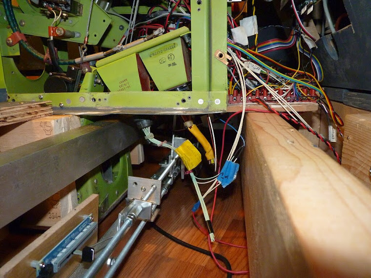
The mechanism works the same way as in Edward's case, however the design is somewhat different, adjusting to my local dimensions and requirements. I had only 200 mm gap between floor and simulator base floor, so I had to fit the mechanism there .
Later I installed two springs.


Turn left (spring removed for greater visibility):

Turn right (of course, depending where from you look at it )
)

Here are the videos:
This video shows the mechanism work with spring removed for greater visibility:
Since I used sliding (60mm) pot from Phidgets, I had to allow ~50 mm linking mechanism travel to simplify pot's movement.
In this video you also can see the sliding pot movements:
Pitch mechanism
January 01, 2014
You all will be laughing
 Here is my pitch amortization design. No springs, no gas springs. Then what? A pair of socks and tennis balls.

6-mm aluminum plate fixed between two hardwood pieces. Pieces may move in front/back direction - that's the way to fine tune the column angle in neutral position.

Two socks with 5 tennis balls each. (Later reduced to 3 balls each - more than enough).

Socks are just tied up together and wrapped around hardwood pieces. Hardwood pieces have small channels to restrict balls moving a bit.

Lower balls are hitting the floor. Top balls push into the sim platform floor through a couple of wood pieces that regulate the gap. In the neutral position (8 degrees forward) both ball rows are just slightly pressed on.

In both extreme positions the force on the yoke reaches above 40 pounds. The force can be regulated by the number of balls. Can't do more precise measurements as light test frame tends to jump itself.

Advantages? Cheap and easy. Absolutely silent movement. Disadvantages? None found so far. .
.

Yokes
April 24, 2014
My 737 linked yokes build practically completed and ready for install into sim.

Main recent development was the actual yokes installation. I bought the yokes from aviasimulation.com. They are 100% copies from 737 yokes and made from hard plastic (same as goes for construction hats). Here is the picture the yokes during production process.

The yokes I have received have all switches are fully wired and have backlighted trip counters. Excellent quality. I am very happy with this acquire. Here are the pictures:

Trim switches are separate:

Trip counter backlighting feeds from 12v.

I also got some other stuff from aviasimulation.com:

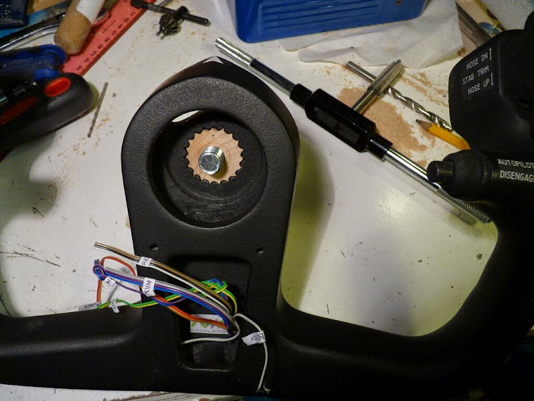
Here is the insert that I made to install the yoke on my column:

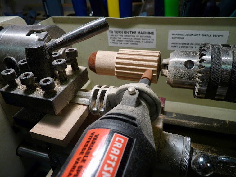
I just bought a couple of furniture legs made of hardwood and made the inserts from them on the lathe.
With some modification to my lathe I managed to make the insert grooves matching the yoke grooves.
I've cut and painted the outer column housings that are made from standard 3" ABS pipes. The outer diameter (90 mm) is a bit bigger that Boeing's. Outer housings are only decorative and do not have any structure supporting functions.

Here is how I completed the yoke wiring:

The existing yoke wires went into a small PCB panel where I added those green connectors. Then the wires go from the green connectors to standard CAT5 network connector:

The installed network cable goes in between the actual yoke column and outer housing. Ground wire is separate, as there are only 8 wires in CAT5 cable.

Finally control column assembly is moving into simulator. I just dragged over from workshop to sim room.
The original frames in the sim base were adjusted for columns assembly placement.
The whole assembly just fits in pre-designed base area and is attached with six 5/16 bolts. When neccessary the whole assembly can be removed from sim for repairs. I already removed it once for some changes. The pitch potentiometer was added only after columns installation. It's the same type Phidgets sliding pot as roll pot, that has been already installed.
I fixed it on one bolt so it can swing, following the path of pitch "arm".
The floor panels around each column area were cut into three pieces to make their removal easier.

Here are a few pictures of installed control columns and TQ.
I installed second spring in roll linking mechanism. (However later I removed it to reduce the turning effort).
DIY Clipboards
December 4, 2014
Here are my Do-It-Yourself clipboards. The clip itself is not exactly like original one (but that can be changed later). I cheated. :) I found in the store the plastic clipboard that I decided to use as a base.
Started with cutting the actual clipboards.
The rest of details were made from usual leftover floor laminate and standard hardware store supplies like hinges, etc.
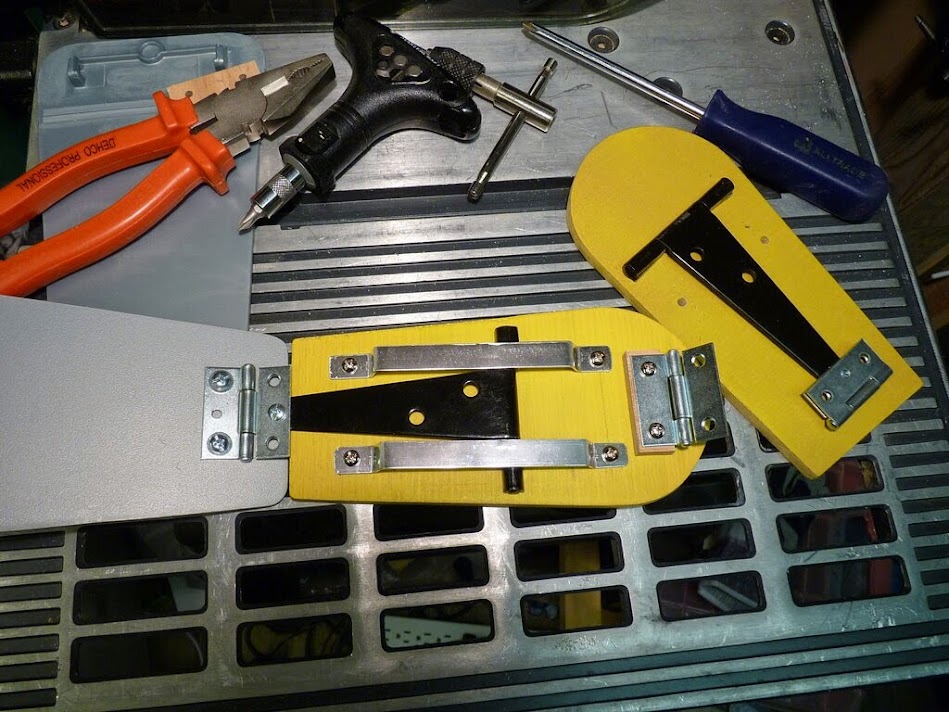
Cut and combined the hinges to create the clipboard supports.
Cut the aluminum "rails from standard angle profile.
Primed and painted the parts:
Not finding anything more suitable I've cut the yellow clipboard pointer from file handle.
The spring is from pen and the ball is 4.5 mm BB gun round. The rail with step holes is made from same aluminum angle profile.
Considering that moving pointer will eventually scratch the clipboard, I glued black pieces of standard plastic file from school supplies over the clipboard.
Now assembling all this together:

The actual text is just printout on laser printer from the MS Word file. You can download the file here. Clipboard attaches with 2 screws that go into the clipboard back through existing holes in yoke.
Both clipboards installed in the cockpit:
January 01, 2014
Here is my dual linked yoke system for my sim. I work on them in my workshop outside the simulator. The wooden box matches the sim's yokes compartment, so the yoke can be just moved into sim compartment later. The whole assembly can also be easily taken out for maintenance.
The mechanical design is based on the info posted by Edward (sluyt050) here.
Work in progress:

The threaded rod was temporarily installed for initial assembly and adjustments:

I tried to use all standard details that can be bought in hardware stores wherever possible. The outer columns supposed to be the familiar 3" ABS pipes from Home Depot :) Their outer diameter is slightly bigger that 76 mm real Boeing column diameter, but they will do. Especially in the dark cockpit.
The standard 1/2" bearings used as top column units and for bottom fittings.
Sawing off the bearing "ears":


There are six 10-tooth chain sprockets used with two #35 chains. Two sprockets for the chain inside each column and two sprockets with the chain connecting the columns. Each chain has two turnbuckles installed for adjustments (thanks for the tip about installing two, Edward! )

The mechanism works the same way as in Edward's case, however the design is somewhat different, adjusting to my local dimensions and requirements. I had only 200 mm gap between floor and simulator base floor, so I had to fit the mechanism there .
Later I installed two springs.


Turn left (spring removed for greater visibility):

Turn right (of course, depending where from you look at it

Here are the videos:
This video shows the mechanism work with spring removed for greater visibility:
Since I used sliding (60mm) pot from Phidgets, I had to allow ~50 mm linking mechanism travel to simplify pot's movement.
In this video you also can see the sliding pot movements:
Pitch mechanism
January 01, 2014
You all will be laughing

6-mm aluminum plate fixed between two hardwood pieces. Pieces may move in front/back direction - that's the way to fine tune the column angle in neutral position.

Two socks with 5 tennis balls each. (Later reduced to 3 balls each - more than enough).

Socks are just tied up together and wrapped around hardwood pieces. Hardwood pieces have small channels to restrict balls moving a bit.

Lower balls are hitting the floor. Top balls push into the sim platform floor through a couple of wood pieces that regulate the gap. In the neutral position (8 degrees forward) both ball rows are just slightly pressed on.

In both extreme positions the force on the yoke reaches above 40 pounds. The force can be regulated by the number of balls. Can't do more precise measurements as light test frame tends to jump itself.

Advantages? Cheap and easy. Absolutely silent movement. Disadvantages? None found so far.
Yokes
April 24, 2014
My 737 linked yokes build practically completed and ready for install into sim.

compare to this previous photo:

The yokes I have received have all switches are fully wired and have backlighted trip counters. Excellent quality. I am very happy with this acquire. Here are the pictures:

Trim switches are separate:

Trip counter backlighting feeds from 12v.

I also got some other stuff from aviasimulation.com:

Here is the insert that I made to install the yoke on my column:

I just bought a couple of furniture legs made of hardwood and made the inserts from them on the lathe.
With some modification to my lathe I managed to make the insert grooves matching the yoke grooves.
I've cut and painted the outer column housings that are made from standard 3" ABS pipes. The outer diameter (90 mm) is a bit bigger that Boeing's. Outer housings are only decorative and do not have any structure supporting functions.

Here is how I completed the yoke wiring:

The existing yoke wires went into a small PCB panel where I added those green connectors. Then the wires go from the green connectors to standard CAT5 network connector:

The installed network cable goes in between the actual yoke column and outer housing. Ground wire is separate, as there are only 8 wires in CAT5 cable.

Finally control column assembly is moving into simulator. I just dragged over from workshop to sim room.
The original frames in the sim base were adjusted for columns assembly placement.
The whole assembly just fits in pre-designed base area and is attached with six 5/16 bolts. When neccessary the whole assembly can be removed from sim for repairs. I already removed it once for some changes. The pitch potentiometer was added only after columns installation. It's the same type Phidgets sliding pot as roll pot, that has been already installed.
I fixed it on one bolt so it can swing, following the path of pitch "arm".
The floor panels around each column area were cut into three pieces to make their removal easier.

Here are a few pictures of installed control columns and TQ.
(I later reduced the number of tennis balls that provide pitch tension to three on each side.)
I installed second spring in roll linking mechanism. (However later I removed it to reduce the turning effort).
DIY Clipboards
December 4, 2014
Here are my Do-It-Yourself clipboards. The clip itself is not exactly like original one (but that can be changed later). I cheated. :) I found in the store the plastic clipboard that I decided to use as a base.
Started with cutting the actual clipboards.
The rest of details were made from usual leftover floor laminate and standard hardware store supplies like hinges, etc.
Cut and combined the hinges to create the clipboard supports.
Cut the aluminum "rails from standard angle profile.
Primed and painted the parts:
Not finding anything more suitable I've cut the yellow clipboard pointer from file handle.
The spring is from pen and the ball is 4.5 mm BB gun round. The rail with step holes is made from same aluminum angle profile.
Considering that moving pointer will eventually scratch the clipboard, I glued black pieces of standard plastic file from school supplies over the clipboard.
Now assembling all this together:

The actual text is just printout on laser printer from the MS Word file. You can download the file here. Clipboard attaches with 2 screws that go into the clipboard back through existing holes in yoke.
Both clipboards installed in the cockpit:


Hi! Where did you get the gear with the threaded rod? The one used in the ball bearings for your yoke?
ReplyDeleteYou can buy the sprockets on eBay or other online store. Mine were 10-teeth for #35 roller chain, 1/2 inch bore. For example:
ReplyDeletehttp://www.ebay.com/itm/35B10H-1-2-Bore-Type-B-Finish-Sprocket-for-35-Roller-Chain-w-keyway-set-screw-/322082865269?hash=item4afda28075:g:8aEAAMXQZ7dTl1zr
Hi Nick
ReplyDeleteGreat Post. Can't thank you enough!
Also, for many photos, seeing Photobucket.com/p600 error jpg instead of your pics. Is there a way you can fix those missing photo links? This is too important a post to miss all those pictures for any new builder trying to follow your foot steps. So, please fix the links.
hi, sir
ReplyDeletenice job, i am planing build yoke 737.can u give dimension