April 2012
Sim base.
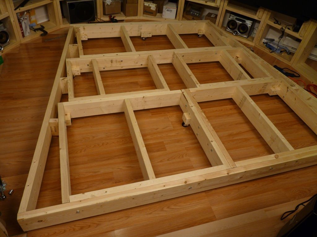
I made sim base exactly match the FDS shell size. I built the base from 6 x 2 lumber. The construction is modular and consists of 5 blocks, screwed together with 8 x 3.5 screws.
Here is my original design of the base and I simplified it somewhat later.

The top is from 6 plywood pieces that were cut from two standard 4’ x 8’ sheets, and painted Boeing grey so far. Later the rubber cover will be added to the base floor.


Additional details about Aura Bass shakers see in Audio Setup page
Sim base.
I made sim base exactly match the FDS shell size. I built the base from 6 x 2 lumber. The construction is modular and consists of 5 blocks, screwed together with 8 x 3.5 screws.
Here is my original design of the base and I simplified it somewhat later.

The top is from 6 plywood pieces that were cut from two standard 4’ x 8’ sheets, and painted Boeing grey so far. Later the rubber cover will be added to the base floor.

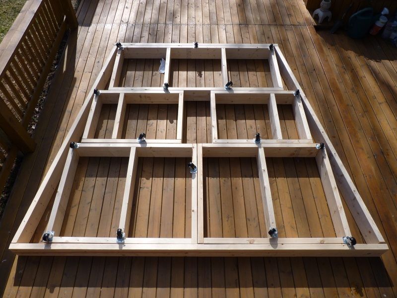
There are 16 casters under the base, 6 of them with the brakes. (later 2 more casters were added)

Total weight of the base is 102 kg . To prevent any floor damage from the base I put another layer of the cheap laminate (that I got on sale ) over the floor.

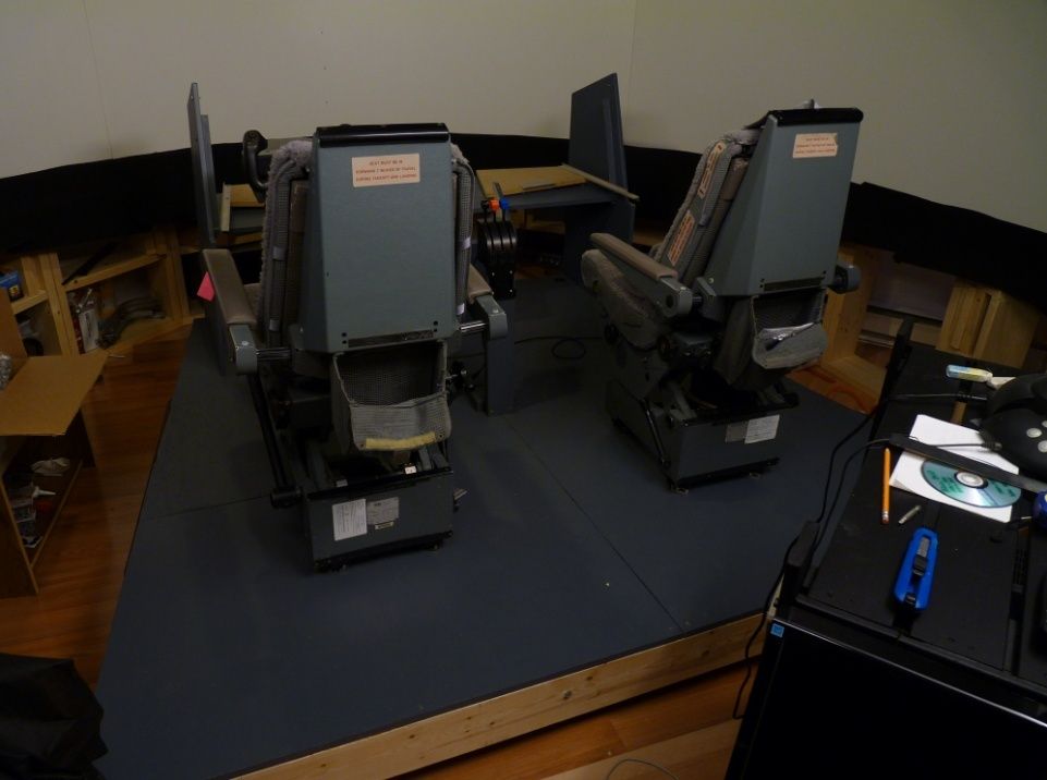
The next sim addition were two IPECO seats from United Airlines 737-300. N304UA.

The seats are in the great shape, In this picture they are not installed on J-rails yet and just stand on the sim base.

Initially I installed temporary fixed yoke post and put my Saitek Pro Yoke on it along with Saitek throttle quadrant. That allowed me to always keep sim flyable during building.

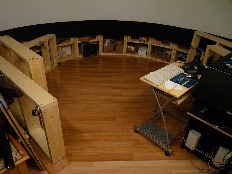
I also built the stand for the main flight PC and two UPS units. It stands behind the sim base.

November 27, 2014
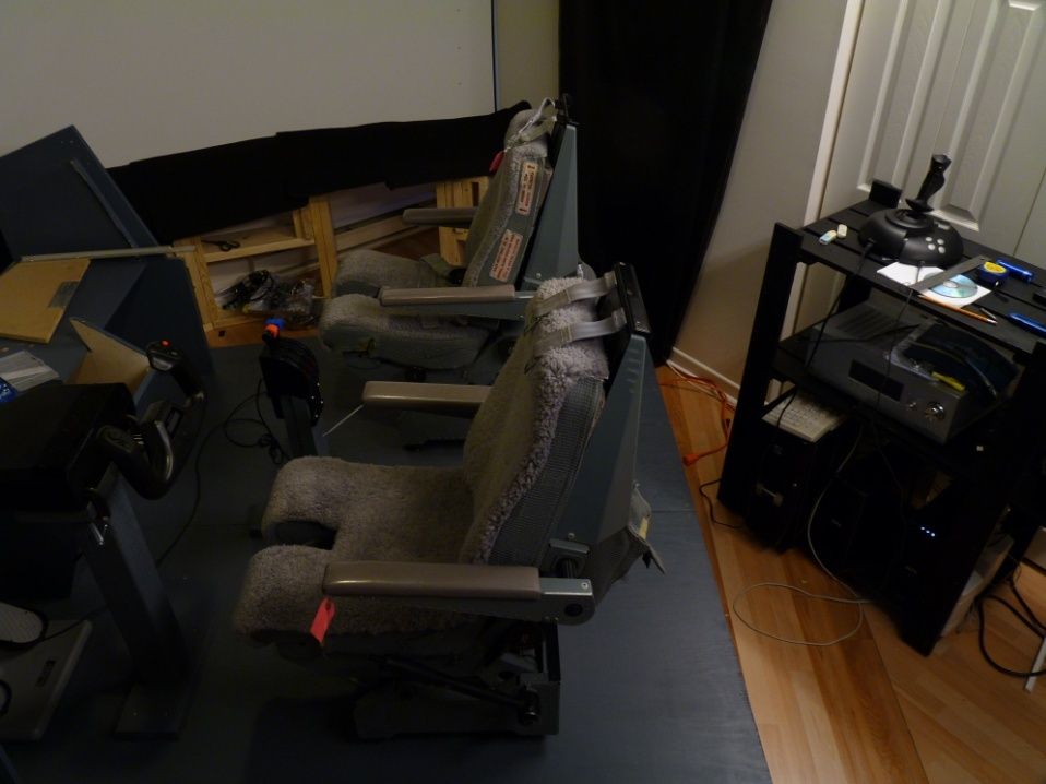
So far I had my IPECO seats just standing on the deck freely. Since there were still lots of tasks to do with the flightdeck (like work with TQ and yoke columns), it was easier to leave seats stand free to move around when neccessary.
Now, after TQ and yoke columns were more or less finalized, I installed my original IPECO J-rails for the seats.
To arrange 4 rails on the flight deck floor the way the seat is in proper position and moves without jams might look challenging, especially while there is no any info of the actual rails layout (at least I was not able to find any).
The best way to do this it to make the "template" board, install the rails and seats on it, check the movement and then copy the arrangement into actual flight deck.
I took a piece of plywood 2' x 4' x 1/2" to use as a template board. First, I cut a part off from it so by size it could fit between the yoke column and the back edge of flightdeck, making it a bit shorter - so you can easily see the alignment mark at the back of flightdeck.
First step is to roughly arrange the rails on template board and then fix the first rail.
When you find the suitable seat location on your board, draw two perpendicular lines on it this way:
Actual distance from the template edges does not really matter, as long as the seat is more or less in the center and its forward position is closer to front edge. In my case it was 150 mm from the right side and 220 mm from the back.
Next, I installed the bigger aft rail (that has the stop holes) the way that one side of its internal cutout is along "vertical" line and the mounting hole is on the "horizontal" line, and fixed it with two screws.
Next, I installed the seat on mounted rail and put the rest of rails into seat's swivel "shoes".
Next, I put the second aft rail so it's mounting hole is also on "horizontal" line, and then aligned this rail by moving seat back and forth.
Next, I fixed this rail with the screw (on the "horizontal" line). Rechecked the seat movement.
Removed the seat and made sure that rails are parallel. Fixed the second aft rail with second screw.
(To tell you a secret, the distance between inner edges of front and aft rails is 222.5 mm. The distance between inner edge of aft rail to the stop holes part of "wide" aft rail is 192 mm.)
Now arrange the position of forward rails. Move the seat forward to the position where aft shoe is at the front end of rail.
Now move the front rail the way the front shoe is also in the similar position. Mark the front rail tip position and then draw another "horizontal" line marking both front rail ends positions. Remove the seat.
Now, when you have all the marking lines, you can simply put the forward end of fwd rail on the marking line and align it with aft rail by placing the long ruler, or a straight plank along both rails side. Mark the holes and put the screws in. Now align the last rail the same way.
The seat movement should be without jams. Make sure that cylindrical side rollers touch the rails.
Next, we move our template board into sim.
Draw the line from the center of yoke column to the end of flightdeck. Put the template board on flightdeck and align it correspondingly. If your flightdeck is made for FDS shell, then the distance from the end of FDS shell to your aft "horizontal" line on the board (or, basically to the ends of aft rails) should be around 235 mm.
When the template board is aligned, just temporary fix it to the flightdeck with a couple of screws . Now you can even install the seat on it and verify the movement.
If everything is good, remove the seat and drill a couple of pilot holes for each rail through the remaining mount holes and straight through flightdeck floor. You can mark the holes that you used right on template. Make sure that you drill exactly vertically - if the hole goes sideways a couple of millimeters, the rail may start to jam or the seat stopper might not properly go into its holes.
Remove the board, remove the rails from it and install the rails on flightdeck using the selected holes.
Done.
Now overturn the template board and repeat the same operations with F/O seat.
This should be even faster since you can reuse the measurements from Captain seat rails.
But note, the location of mounting holes at the end of "wide" aft Capt and F/O rails is not exactly "mirrored".
Whole operation takes about an hour per seat.
December 12, 2014
IPECO seat is a complex thing and I did not want to change it in any way or even drill the additional holes in it to attach Aura Bass shakers.
I build the additional wooden structure that fits tight under the seat and uses existing holes to attach it in place.
Tight fit is necessary, since it supposed to pass the vibrations to the seat. Aura Bass shaker is attached to the wood.
In front it's attached in four places by the screws holding down the metal brackets against the seat structure.
In the back there are two long 5/16" bolts that go through additional MDF plank located under the seat cushion.
So, this structure can be easily removed when needed. The shaker wire goes freely through the small hole drilled under the seat in the sim base floor. The seat movements are not affected by this installation in any way.
Additional details about Aura Bass shakers see in Audio Setup page
Do you know anyone selling J rails ? I have IPECOS like yours without rails...
ReplyDelete